Standard components

The system comprises of the following:

Windlass, 12 volt DC:   Fixed into the underside base plate with 4 x M8 S/S studs supplied, or longer M8 bolts as the fitter may employ to suit the installation.  The windlass may be fitted in many different positions on yachts, typically at the base of the mast, or in a stern locker, or anywhere permitting the halyard to run through pulley blocks up to a lifting point. We make recommendations for each different yacht. Comes with 2 wiring tails of 500mm each. Windlass current consumption with 110-130Kg load on standard 2:1 reduction:

  • Inrush up to 70A for 2 seconds, then 17 to 25A through the lifting load cycle.
  • Inrush up to 40A for 1.5 seconds, then 10 to 12A through launch cycle.

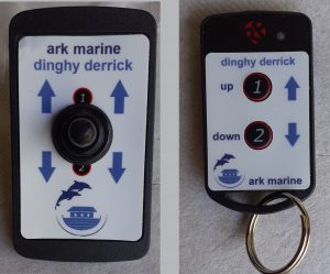
Pendant pushbutton control (one supplied):   CR2450 3V battery operated. Operational range subject to battery condition but ARK test rig works at 9 to 12 metres away from receiver.

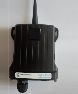
Radio receiver:     12-24 V DC   To mount inside yacht in any location except close to engine or compass or waterline. To be installed with 2 fuses (not supplied)

  • Radio circuit with in line 1 amp quick radio fuse.
  • Switching circuit with in line 4A (12VDC) or 2A (24VDC) fuse of any type.

Deck switch:       12-24V DC.  Waterproof spring toggle switch for panel mount inside or on helm panel.

Changeover contactor:    Protection IP66.  Activated by either radio receiver or deck switch.  To mount inside yacht in any location.

The lifting and launching are powered by this electric waterproofed rope windlass which can be located in various positions on deck or even in a locker.
he electrical system supplied comprises of:  (top left clockwise):  Changeover contactor (12 V DC),   Radio receiver,   Deck switch used as an alternative to the remote,   Pushbutton remote control   with  necklace and pocket clip.


Optional components

(see Price List for costings)

  1. Windlass, 24 volt DC of same pattern as 12V standard.
  2. Extra heavy duty 24V windlass for mounting in locker or concealed location. Deck mounted version also available – contact us to discuss.
  3. Pendant pushbutton control: Theoretically up to 50!! extra units maybe purchased and employed to tune into the radio receiver.
  4. Changeover contactor: 24V DC
  5. External antenna to fit the radio receiver and improve reception (in reality this should never be needed except in exceptionally shielded installation positions).
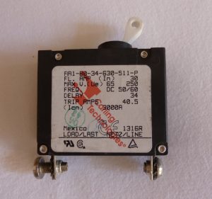
  6. Magnetic-hydraulic circuit breaker (as photo), slow response: Carling Tech model AA1-B0-34-630-511-P  for 12 or 24V use.
  7. Cabling not supplied: We recommend minimum 16 sq.mm copper stranded PVC insulated for maximum of 10 metre run from contactor to windlass.  Resize if run exceeds this, chosen not to exceed 5% total voltage drop.  An online calculator such as this is a useful tool.
A circuit breaker, long delay type, is required but not supplied by Ark as standard because users may prefer commonality with their existing C/B set up and may have spare panel space for one.   The C/B is an optional extra and we supply the Carling AA series, either 30 or 40 Amp rated.